Beginner’s guide · Make & build
Prove the circuit first,
then route the board around real footprints.
A tiny LED board can move from tested schematic to KiCad layout, design-rule checks and fabrication files without pretending software catches every electrical mistake.
Quick answer
Complete one fabrication-ready low-voltage board before expanding the setup
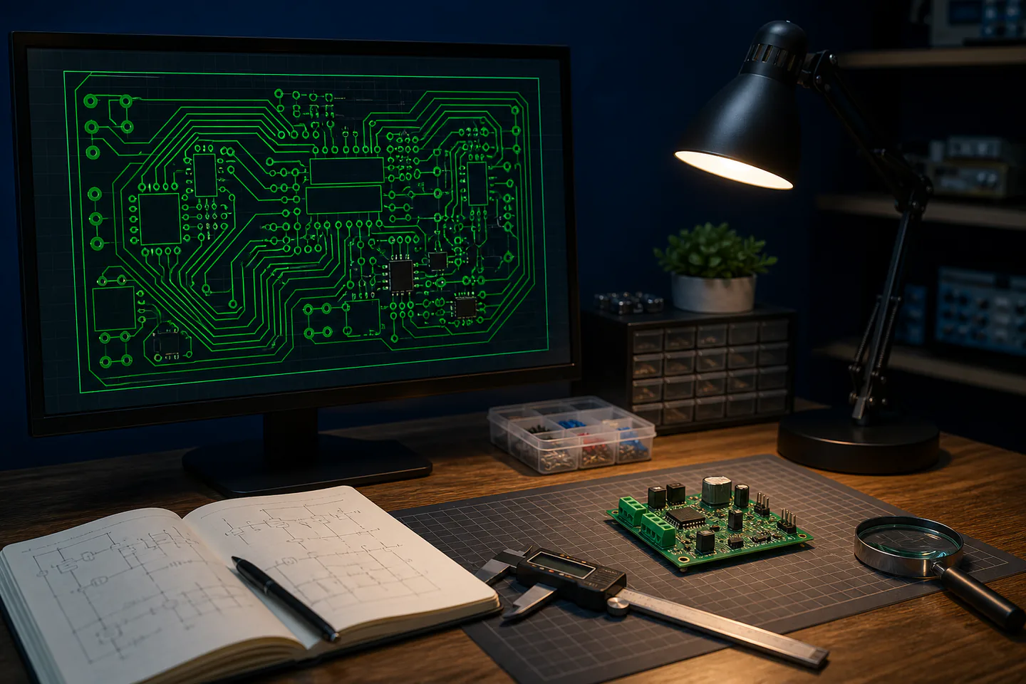
Breadboard and measure a simple battery-powered LED circuit first, create a KiCad project, redraw the known schematic, assign footprints from the actual component datasheets, run electrical rules checking, place connectors and mechanical features before routing, set the chosen fabricator’s minimum widths, clearances and drill sizes, route a two-layer board, run design rules checking and inspect the Gerber and drill outputs before asking an experienced reviewer to compare them with the tested circuit.
- 01
A schematic describes intended electrical connections; the board layout is their physical implementation. Record what happened during pcb design so the next attempt changes one known variable instead of several guesses.
- 02
A symbol can be electrically correct while its assigned footprint has the wrong pin numbering or dimensions. Record what happened during pcb design so the next attempt changes one known variable instead of several guesses.
- 03
ERC and DRC find defined rule violations, not every design, power, thermal or component-choice mistake. Record what happened during pcb design so the next attempt changes one known variable instead of several guesses.
- 04
Fabrication limits, assembly method and actual datasheets must be known before routing, not after export. Record what happened during pcb design so the next attempt changes one known variable instead of several guesses.
What to expect
What pcb design is really like at the start
The useful beginner controls are preparation, one bounded task and a record of the result; specialist equipment matters only when it solves a repeated limitation.
Library
A familiar symbol name does not guarantee the package, pitch, orientation or pin numbering of the purchased part. Record what happened during pcb design so the next attempt changes one known variable instead of several guesses.
Placement
Connector access and return-current paths matter before attractive routing. Record what happened during pcb design so the next attempt changes one known variable instead of several guesses.
Rules
Default widths and clearances may not match the chosen board house or current. Record what happened during pcb design so the next attempt changes one known variable instead of several guesses.
Output
A Gerber viewer can reveal missing outline, mask or drill files but cannot prove the circuit will work. Record what happened during pcb design so the next attempt changes one known variable instead of several guesses.
Core method
The core pcb design method
Start from measured behaviour
Record the supply, current, polarity and component values of a low-voltage breadboard circuit. Record what happened during pcb design so the next attempt changes one known variable instead of several guesses.
Build the schematic and footprint evidence
Use manufacturer datasheets to assign packages and verify every numbered pin. Record what happened during pcb design so the next attempt changes one known variable instead of several guesses.
Place before routing
Fix board outline, holes, connectors and high-priority loops, then route power and signals deliberately. Record what happened during pcb design so the next attempt changes one known variable instead of several guesses.
Check the release package
Resolve ERC and DRC findings, inspect Gerbers and drill files and obtain an independent schematic-to-layout review. Record what happened during pcb design so the next attempt changes one known variable instead of several guesses.
Useful products
Products with a clear job in the route
The meter verifies the prototype, the caliper checks real packages and the soldering iron becomes relevant only if the first board will be hand assembled.
AstroAI TRMS 6000-Count Digital Multimeter
It turns wiring and power faults into separate testable questions.
Kynup Digital Caliper, 150 mm
It makes small fit differences visible instead of relying on feel.
Antex XS25 25 W Soldering Iron
It is suitable for short supervised electronics tasks when paired with a stable stand and extraction.
First project
Design a two-layer battery LED board
Use through-hole parts with accessible datasheets and make the schematic identical to a working breadboard.
- 01
Prove and record the circuit
Measure supply polarity, LED current and resistor value on a protected low-voltage breadboard. Record what happened during pcb design so the next attempt changes one known variable instead of several guesses.
- 02
Capture the schematic
Name nets, annotate parts, add power flags deliberately and resolve every ERC item. Record what happened during pcb design so the next attempt changes one known variable instead of several guesses.
- 03
Verify footprints
Print or measure packages at one-to-one scale and compare pin numbers with manufacturer drawings. Record what happened during pcb design so the next attempt changes one known variable instead of several guesses.
- 04
Place and route
Set the board outline and fabrication rules, place mechanically and route the simplest current paths. Record what happened during pcb design so the next attempt changes one known variable instead of several guesses.
- 05
Inspect and review outputs
Run DRC, open every Gerber and drill file and have another person compare board and schematic. Record what happened during pcb design so the next attempt changes one known variable instead of several guesses.
What can wait
What can wait until the first result
Delay anything that adds cost, risk or another variable before the basic workflow has produced something you can review.
- 01
Mains voltage
Clearance, creepage, isolation, protection and legal duties require qualified design and test. Record what happened during pcb design so the next attempt changes one known variable instead of several guesses.
- 02
USB high speed and RF
Signal integrity and controlled impedance exceed a first visual routing exercise. Record what happened during pcb design so the next attempt changes one known variable instead of several guesses.
- 03
Tiny surface-mount packages
Assembly yield can hide design learning behind rework difficulty. Record what happened during pcb design so the next attempt changes one known variable instead of several guesses.
- 04
Panelisation and production
Fabricator-specific tooling, test and process control follow a successful single prototype. Record what happened during pcb design so the next attempt changes one known variable instead of several guesses.
Upgrade path
Add the capability you can now name
Each stage should remove a demonstrated constraint rather than make the setup look more advanced.
Use what you own
£0–£20Existing equipment and one written plan
Copy and understand one documented low-voltage circuit.Repeat the first route
Free software; about £20–£80 prototype and toolsA complete repeatable starter setup
Create and review a simple two-layer through-hole board.Add one capability
Often £50–£250One selected tool, service or learning resource
Order, assemble and measure one prototype revision.Build specialist depth
Club, course or specialist dependentA documented specialist workflow
Add four layers, fine-pitch parts or controlled impedance with experienced review.Safety & care
Software checks defined rules, not the whole engineering decision
Power, heat, isolation, component ratings and assembly still require explicit evidence.
- Keep the first design battery-powered and current-limited and do not design mains, medical, automotive or safety-critical hardware as a beginner.
- Use current manufacturer datasheets and stay within absolute maximum, thermal and polarity ratings.
- Inspect meter leads and use the correct sockets and function before low-voltage measurements.
- Use fume extraction, a stable stand and eye protection if assembling the board by soldering.
- Mark revision and polarity clearly and power the first assembled board through current limiting.
Outside help
When outside help earns its place
A makerspace PCB review is valuable immediately before fabrication because another person can catch footprint, connector and rule assumptions.
Choose a session that reviews native KiCad files, Gerbers and actual part datasheets rather than only appearance.
Use outside help after the first pcb design attempt can reveal the exact technique, access or safety problem that needs live correction.
Representative UK learning and access routes checked 1 September 2026; local prices, permissions, equipment and tutor support vary.
Sources
Where the guidance came from
Authoritative and specialist guidance supports the method and safety boundaries; community discussion contributes recurring beginner problems rather than unsupported claims.
-
01
KiCad · Getting started
Official schematic, layout, ERC, DRC and fabrication workflow.
Open source -
02
KiCad · PCB Editor
Board setup, routing, rules and fabrication output reference.
Open source -
03
KiCad · Schematic capture
Symbol, wiring and electrical-rule-check concepts.
Open source -
04
KiCad · Documentation
Current manuals and version-specific references.
Open source -
05
HSE · Electronics soldering
Solder-fume hazards and control.
Open source -
06
Reddit · r/KiCad
Community evidence on footprint mistakes, design-rule setup and first-board review.
Open source -
07
Amazon UK · TRMS 6000-Count Digital Multimeter
Exact Amazon UK product page or ISBN used for this recommendation; current price, seller, specification and availability should be confirmed.
Open source -
08
Amazon UK · Digital Caliper, 150 mm
Exact Amazon UK product page or ISBN used for this recommendation; current price, seller, specification and availability should be confirmed.
Open source -
09
Amazon UK · XS25 25 W Soldering Iron
Exact Amazon UK product page or ISBN used for this recommendation; current price, seller, specification and availability should be confirmed.
Open source
Guide information and links checked 1 September 2026.