Beginner’s guide · Make & build
Build one effect,
then trace every signal.
Start with a documented low-voltage kit or a simple breadboard boost, not a mystery schematic. Careful solder joints, polarity checks and staged testing matter more than a painted enclosure.
Quick answer
Choose a complete low-voltage kit with a verified build document
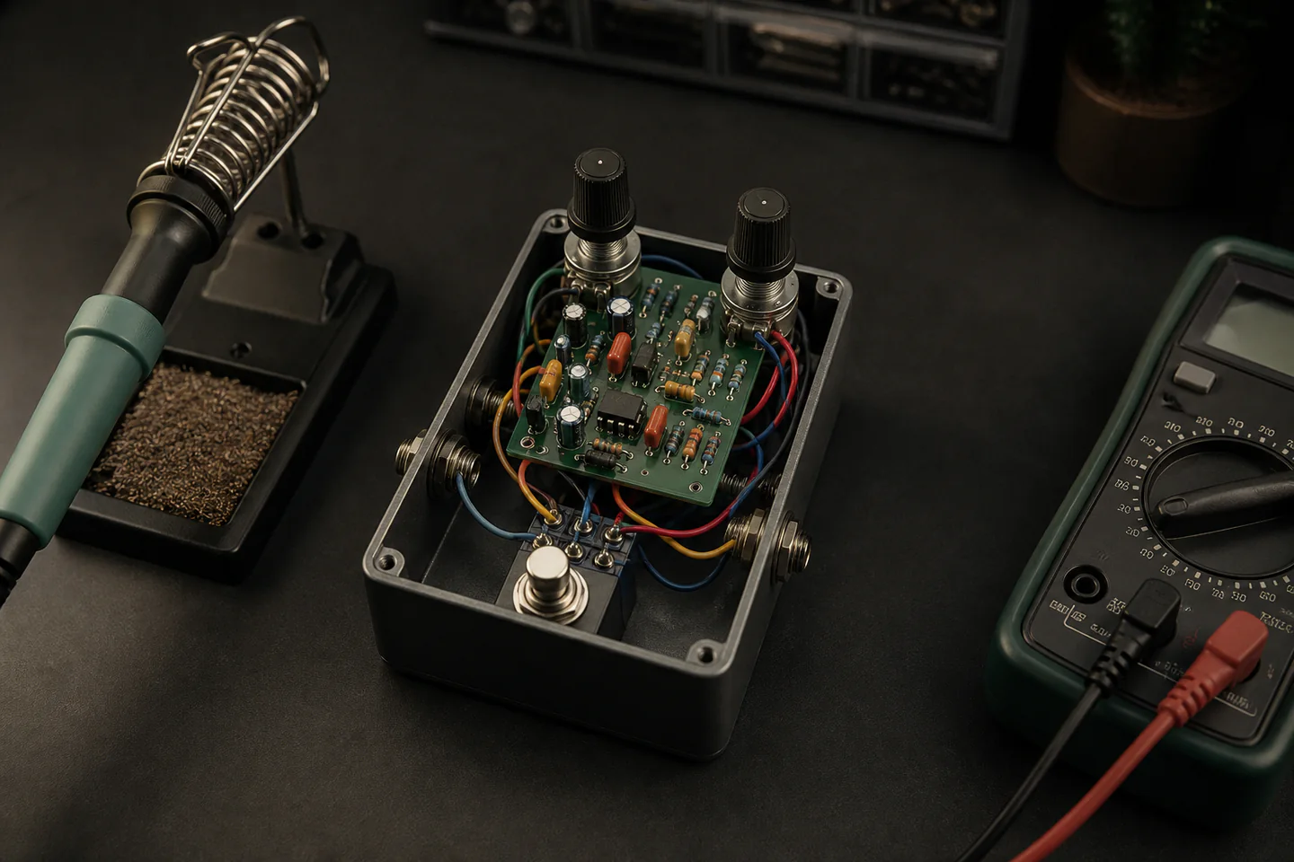
Buy a reputable beginner kit or PCB whose bill of materials, component values, wiring diagram, enclosure drill template and troubleshooting notes are available before purchase. Practise soldering spare wire or a small training board, then populate the lowest components first, checking every resistor value, diode direction, electrolytic polarity and transistor orientation. Test the circuit from a current-limited 9 V supply or battery before final enclosure wiring, and never use the project as an excuse to work on a mains-powered amplifier.
- 01
The pedal circuit is normally low voltage; the connected amplifier is not. Keep all DIY work outside mains equipment.
- 02
A documented kit from a specialist seller is a better first project than a random bag of parts with only a tiny diagram.
- 03
Component orientation and off-board wiring cause many failures. Photograph and inspect each stage before hiding it in an enclosure.
- 04
Ventilate soldering work, wash hands after handling solder and flux, and keep a stable iron stand and eye protection at the bench.
- 05
A multimeter and an audio probe solve more problems than replacing components at random.
What to expect
Most failed first pedals contain one ordinary build error
Wrong resistor value, reversed diode, cold joint, solder bridge, swapped jack lug or missing ground are all more likely than a mysterious design fault.
Reading
Colour codes and tiny markings are easy to misread. Measure resistors before fitting and sort components into labelled groups.
Solder
Heat pad and lead together, feed only enough solder for a smooth concave joint and stop before the pad lifts.
Polarity
Diodes, electrolytic capacitors, LEDs, transistors and ICs can have different orientation conventions. Follow the exact PCB document.
Wiring
Input, output, ground, footswitch and DC jack lugs are spatially confusing; continuity-test instead of guessing.
Noise
Long loose wires, poor grounding and an unsuitable supply can add hum even when the effect works.
Troubleshooting
Confirm power and bypass first, then follow signal from input to output. Changing many parts at once destroys the evidence.
Core method
Turn the schematic into checkpoints you can verify
Choose support before tone
Read the full build document and forum history for a candidate boost or silicon fuzz. Confirm it uses a 9 V DC supply, standard available parts and a PCB or stripboard layout suited to beginners. Avoid projects with mains voltage, obsolete rare transistors or no measured voltages. Buy the exact parts list rather than substituting silently.
Practise the physical joint
Set the temperature specified for the solder and board, use local fume extraction or effective ventilation and tin a few pieces of spare wire. A good joint wets both surfaces without a ball, spike or bridge. Learn to clean the tip and use the stand every time before touching the real PCB.
Populate and inspect in stages
Measure and fit resistors first, then sockets, diodes, capacitors and active parts in the documented order. Clip leads only after the joint has cooled. Use magnification to inspect both sides and compare every polarity mark with the build sheet before adding pots or switch wiring.
Test before decoration
Check resistance from power to ground for an obvious short, then use a protected 9 V source and measure the documented supply points. Test bypass, effect output and controls outside or loosely inside the enclosure. If it fails, make an audio probe from the specialist instructions and follow the signal one stage at a time.
Useful products
Products with a clear job in the setup
These recommendations are bench tools, because a first effect circuit should come from a specialist kit seller whose current PCB, parts and documentation are matched. The Antex iron has a manageable fixed output, the stand prevents a hot tool rolling across the bench and the multimeter supports polarity, continuity and voltage checks. Add suitable solder and extraction according to the chosen build.
Antex XS25 25 W Soldering Iron
It is a recognised UK electronics tool and its modest power suits the through-hole work common in beginner kits.
Antex ST4 Soldering Iron Stand
A stable rest reduces burns, cable snags and accidental contact with components.
AstroAI TRMS 6000-count Digital Multimeter
Even a simple meter turns wiring and voltage questions into evidence and remains useful for later electronics.
First project
Assemble and test one documented boost circuit
A low-parts-count boost produces an audible result while leaving each circuit stage visible.
- 01
Inventory the kit
Match every part to the bill of materials and measure ambiguous resistors.
- 02
Practise five joints
Use spare wire or a training board and inspect the shape under good light.
- 03
Populate low to high
Fit resistors and diodes before tall capacitors, sockets and controls.
- 04
Verify polarity and power
Check orientation, continuity and power-to-ground resistance before applying 9 V.
- 05
Test audio in stages
Confirm bypass, power LED, effect signal and each control before final assembly.
- 06
Box without twisting wires
Fit hardware gently, protect the board and retest after the enclosure closes.
What can wait
What can wait until the first result
Cosmetic and boutique parts can wait until the circuit works and the builder can explain why.
- 01
A custom painted enclosure
Drilling, finishing and artwork add work without helping a silent circuit pass signal.
- 02
Rare vintage transistors
Known modern parts make a first build repeatable and easier to diagnose.
- 03
A large pedalboard supply
A battery or protected centre-negative supply specified by the kit is enough for testing.
- 04
Surface-mount circuits
Through-hole parts are easier to identify, handle and probe at the beginning.
- 05
Amplifier modification
Mains and stored high voltage require a different level of training and are outside this hobby route.
Upgrade path
Upgrade the repeated limitation
Upgrade only where repeated builds reveal a bottleneck in heat control, diagnosis or enclosure work.
First documented kit
About £55–£120Basic iron, stand, meter and one kit
Learn joints, polarity and staged test.Repeatable bench
About £120–£260Temperature-controlled station, extraction and magnification
Improve joint consistency and comfort.Debugging bench
About £180–£450Audio probe, protected supply and signal source
Trace faults and compare stages.Enclosure production
About £300–£1,000+Drill press, step bits, jigs and finishing controls
Build neat repeatable hardware safely.Safety & care
Keep the project low voltage and the bench controlled
A 9 V pedal is a suitable electronics project; an opened amplifier or improvised mains supply is not. Heat, fumes, sharp leads and batteries still need deliberate controls.
- Do not open, modify or probe mains amplifiers, wall adapters or other high-voltage equipment; capacitors can retain dangerous charge.
- Use local solder-fume extraction or effective ventilation, avoid breathing flux smoke, wash hands and keep food and drink off the bench.
- Wear eye protection when clipping leads, hold the board securely and place every hot iron in a stable compatible stand.
- Use only the polarity, voltage and current arrangement specified by the circuit; inspect batteries and disconnect power when unattended.
- Check component and solder safety data, collect clipped leads and electronic waste, and do not wash flux or metal residue into household food areas.
Outside help
When outside help earns its place
A well-supported kit forum can carry the first boost. A soldering workshop is valuable if the learner cannot yet recognise a good joint or wants supervised access to extraction and test equipment.
Choose a seller that publishes layouts, voltages and troubleshooting support.
Ask about extraction, test equipment, low-voltage scope and the take-home circuit.
Representative UK learning options checked 17 August 2026; local prices, access, materials and tutor support vary.
Sources
Where the guidance came from
UK safety guidance defines fume and electrical boundaries; specialist pedal builders and experienced communities provide the circuit-specific documentation and recurring fault evidence.
-
01
HSE · Solder fume and rosin-based fluxes
UK health guidance on solder-fume exposure and control.
Open source -
02
Electronics Club · Soldering guide
Clear through-hole soldering, tools and joint inspection guidance.
Open source -
03
Aion FX · DIY guitar pedal resources
Documented pedal projects, schematics and troubleshooting material.
Open source -
04
FuzzDog · Pedal parts and kits
UK specialist kit and PCB context with build documentation.
Open source -
05
Reddit · r/diypedals
Community evidence on first circuits, wiring mistakes and diagnosis.
Open source -
06
Amazon UK · XS25 25 W Soldering Iron
Exact product catalogue page or ISBN used for the recommendation; current price, seller and availability should be confirmed.
Open source -
07
Amazon UK · ST4 Soldering Iron Stand
Exact product catalogue page or ISBN used for the recommendation; current price, seller and availability should be confirmed.
Open source -
08
Amazon UK · TRMS 6000-count Digital Multimeter
Exact product catalogue page or ISBN used for the recommendation; current price, seller and availability should be confirmed.
Open source
Guide information and links checked 17 August 2026.