Beginner's guide · Make & build
Make one clean joint.
Then make it repeatable.
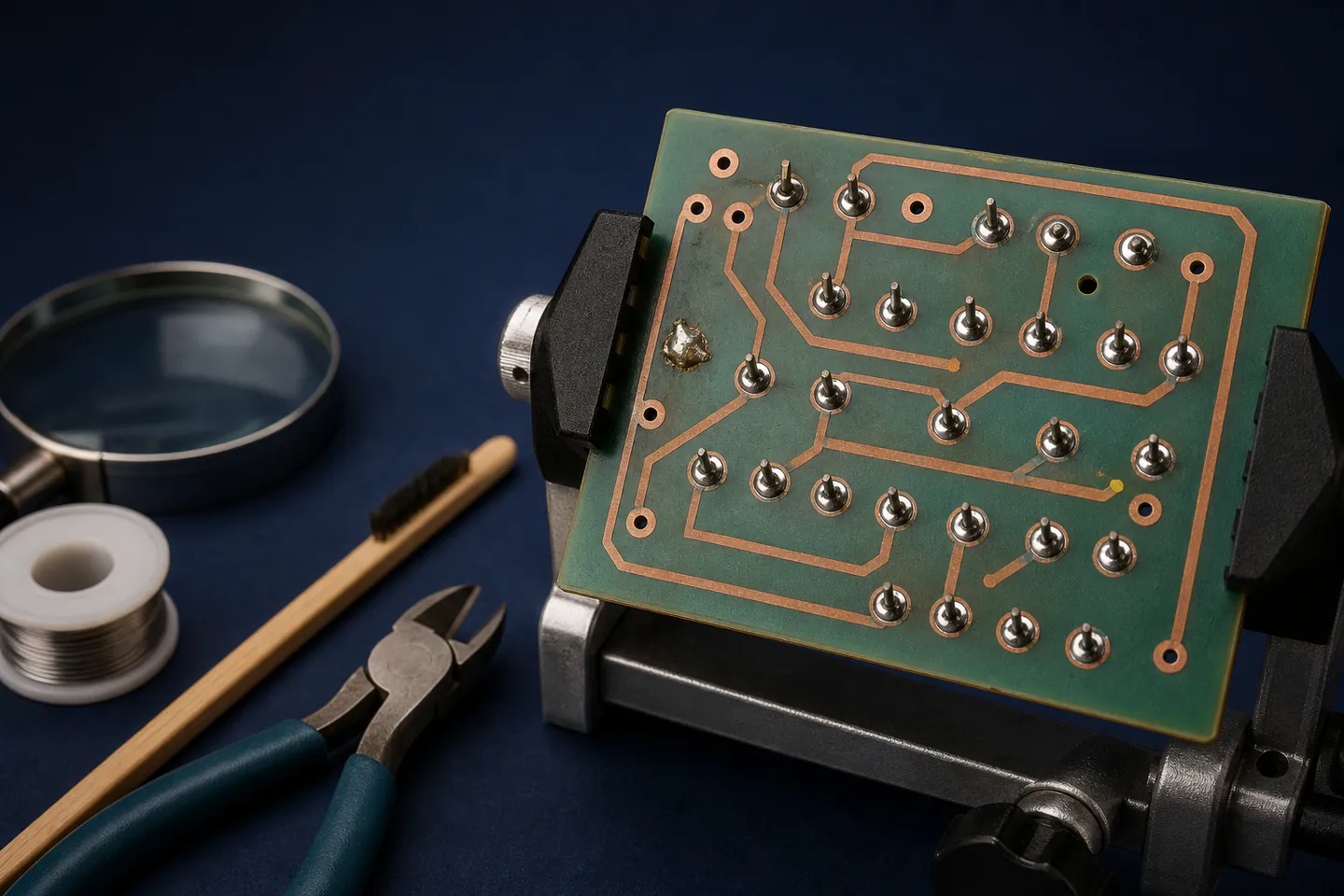
Start on a low-voltage through-hole practice kit with a stable iron stand, lead-free solder and strong ventilation. Learn to heat the pad and component together, inspect the joint, trim safely and diagnose one fault at a time.
Quick answer
Make one clean joint.
Practise on a clearly documented low-voltage through-hole kit, not a household appliance. Put the iron in a weighted stand, work with local fume extraction or effective control, wear eye protection, keep the head out of the rising flux plume and wash hands after handling solder. Heat the pad and lead together, feed a small amount of solder into the joint and inspect it before moving on.
- 01
The smoke seen while soldering is mainly heated flux, not a harmless sign that the joint is working. HSE identifies rosin-based flux fume as a serious occupational asthma risk.
- 02
Lead-free solder avoids deliberately introducing lead to the starter bench, but flux, heat and hand hygiene still matter. Never eat or drink at the work area.
- 03
A basic fixed-power iron can complete a first kit when used carefully; temperature control becomes valuable for repeat work and delicate pads.
- 04
A multimeter is for low-voltage continuity and measurement after its instructions are understood. It does not make mains circuits a suitable beginner project.
What to expect
What the first attempts really involve
Good soldering is a sequence of clean surfaces, enough heat, short contact and inspection. Buying a powerful iron cannot correct a contaminated tip, an unsupported board or a component fitted backwards.
Heat transfer
The iron heats the copper pad and component lead; solder then flows over both. Melting solder only on the tip often leaves a weak blob sitting on one surface.
Flux fume
Flux makes metal wettable but its heated fumes can harm breathing. General room air is not the same as capturing fumes before they enter the breathing zone.
Polarity
Diodes, LEDs, electrolytic capacitors and integrated circuits may have a required orientation. The board marking and kit instructions must agree before soldering.
Mechanical support
A moving component creates a disturbed joint. Bend leads lightly or use a holder so the part stays against the board until the solder solidifies.
Fault-finding
Most first-kit faults are visible: missed joints, bridges, reversed parts, damaged pads or wrong values. Power cycling without inspection can make damage worse.
Fundamentals
Build the first attempt on reliable fundamentals
Keep the first circuit low voltage
Choose a kit powered by batteries or a supplied low-voltage connection and containing large through-hole parts. Do not practise inside a plug, mains power supply, microwave, charger or lithium battery pack. High voltage can remain present after disconnection, and a beginner cannot infer safety from the size of a circuit.
Control the hot and airborne hazards
Place the stand on a clear, heat-resistant bench and route the cable so it cannot drag the iron. Use appropriate extraction close enough to capture the flux plume, keep the face out of its path and avoid overheating. Safety glasses help with clipped leads and unexpected solder spit. Return the iron to the stand every time it leaves the joint.
Prepare the tip and joint
Fit the correct clean tip while cold, heat the iron, add a very small coat of solder and wipe it using the stand's approved cleaner. Insert and check the component, touch the tip so it contacts pad and lead together, then feed solder into the heated joint. Remove solder first and the iron second; keep the part still while the smooth fillet freezes.
Inspect before applying power
Use bright light and magnification. A useful joint wets both surfaces and does not touch its neighbour. Check polarity, values and every required position against the instructions. With the circuit unpowered, continuity mode can identify an accidental bridge, but it cannot prove the full circuit is correct. Set the meter lead sockets and range before measuring.
Useful products
A stable hot-tool setup and a forgiving first circuit
The Antex iron and matching stand cover controlled handling, the lead-free solder provides a known consumable and the low-voltage FM-radio kit supplies a concrete through-hole task. The AstroAI multimeter is connected to the upgrade path because diagnosis is useful after basic meter safety and circuit reading are understood.
Antex XS25 25 W Soldering Iron
It can make ordinary through-hole joints without pretending that an expensive station is essential for one kit.
Antex ST4 Soldering Iron Stand
A predictable resting place prevents cable movement and accidental contact during every joint.
HR Lead-free Solder Wire, 0.8 mm, 60 g
The diameter makes controlled small feeds easier than thick general-purpose solder.
EK DIY FM Radio Electronic Soldering Kit
It provides repeated through-hole joints and an outcome more informative than random practice pads alone.
First circuit
Build one low-voltage through-hole radio kit
Read the entire kit manual before heating the iron. Sort components by reference and value, then solder from the lowest-profile parts to the taller parts unless the kit specifies another order.
- 01
Prepare the bench
Set the stand, extraction, eye protection, light and a heatproof clearance zone before plugging in the iron.
- 02
Inventory the kit
Match each component to the bill of materials and identify every polarity mark without relying on colour alone.
- 03
Practise on spare copper
Make several joints on scrap stripboard or supplied practice pads until a small smooth fillet can be repeated.
- 04
Fit the first parts
Insert the lowest components, support the board and retain leads lightly so nothing moves while a joint cools.
- 05
Heat both surfaces
Contact pad and lead, introduce only enough solder to wet them, then remove solder and iron cleanly.
- 06
Inspect every group
After three or four components, check for missed pads, dull disturbed joints, bridges and heat damage under bright light.
- 07
Trim safely
Wear eye protection, hold the waste end and cut leads so they cannot fly across the room or remain as sharp spikes.
- 08
Power once with a plan
Complete the manual's pre-power checks, use only the specified supply and disconnect immediately if a component heats, smells wrong or the circuit behaves abnormally.
Troubleshooting
Read the result before changing the setup
A solder blob needs reheating of the joint
Add a little fresh flux only if the materials permit, place the clean tinned tip against pad and lead together and let the existing solder flow. Do not keep piling solder onto a cold connection.
A bridge needs removal, not scraping
Disconnect power, use solder wick or a proper pump with controlled heat and inspect between tracks afterwards. Scraping with a knife can cut the board or lift copper.
A lifted pad is a stop signal
Excess heat or force can detach copper from the board. Do not improvise a wire repair on a powered circuit; photograph it and obtain model-specific repair advice.
A silent kit should be checked systematically
Verify supply voltage and polarity, then compare component orientation and joint completeness with the diagram. Change one condition at a time and record meter readings rather than reflowing every joint blindly.
Skip for now
What can wait
The first project should teach joints and inspection without adding hazardous voltages or difficult packages.
- 01
Mains-powered repair
Disconnected appliances can retain dangerous energy and safety depends on insulation, earthing and testing. It is outside this beginner route.
- 02
Lithium battery building
Short circuits, unsuitable chargers and damaged cells can cause intense fires. Use complete protected products and never solder directly to an unknown cell.
- 03
Tiny surface-mount components
They require different handling, magnification and often hot-air or paste workflows. Through-hole work makes the same electrical ideas easier to see.
- 04
A large component assortment
A documented kit gives every part a purpose. Random values become useful only after circuit reading and breadboard experiments begin.
Upgrade path
What a better setup changes
Upgrade when the limitation can be named: unstable temperature, poor visibility, slow diagnosis or a need to prototype before soldering.
First through-hole kit
About £60–£75Iron + stand + solder + low-voltage kit + extraction
Teaches repeatable joints, orientation, inspection and safe bench habits.Measured fault-finding
Add about £20–£35Multimeter + test leads + documented low-voltage circuit
Adds continuity, resistance and voltage evidence instead of visual guesses.Temperature-controlled station
Often £60–£150Regulated station + replaceable tips + better holder
Improves recovery and repeatability across joints without replacing technique.Prototype and repair bench
VariesBreadboard, bench supply with current limit, magnification and desoldering tools
Supports circuit experiments and controlled fault isolation after core safety is established.Before upgrading
A useful check before spending more
Separate assembly from circuit design
A kit can teach placement and soldering even when the circuit theory is not yet familiar. After it works, trace the power path and one signal stage instead of pretending assembly alone explains the electronics.
Use measurements only within the meter's rating
Before each reading, check lead sockets, function and expected range. If the voltage category or circuit hazard is not understood, do not connect the meter and seek qualified instruction.
Safety
Heat, fumes and electricity need firm boundaries
A tidy bench prevents many accidents, but fume control and voltage limits are not optional presentation details.
- Use effective fume extraction, keep the head out of the plume and stop if fumes cause breathing or skin symptoms.
- Wear eye protection, return the iron to its weighted stand and treat the tip and freshly soldered leads as hot.
- Wash hands after soldering; keep food, drink and face-touching away from the bench.
- Work only on low-voltage circuits whose supply and polarity are documented.
- Never modify mains equipment, microwave ovens, high-voltage capacitors or lithium battery packs from this guide.
- Unplug the iron after use, allow it to cool in the stand and store clipped leads and solder safely.
Classes
When outside help is useful
A supervised session is valuable when the first joints remain inconsistent, before using a multimeter on unfamiliar equipment, or before moving to surface-mount work. It is the right route for mains qualifications rather than an optional final flourish.
Look for extraction, through-hole practice, joint inspection and supervised desoldering.
Useful when it covers breadboarding, current-limited supplies and measured fault-finding on low voltage.
Representative UK makerspace and adult-learning formats checked 30 July 2026; tools and take-home kits vary.
Sources
Sources and checking notes
HSE guidance establishes the fume boundary, specialist tutorials cover joint technique, fire-service advice informs battery cautions and direct listings identify the exact starter equipment.
-
01
HSE · Electronics soldering
Official guidance on rosin flux fume, asthma risk, extraction and posture.
Open source -
02
HSE · Solder fume and you
Official employee guidance on controlling exposure to solder fume.
Open source -
03
Adafruit · Guide to excellent soldering
Detailed beginner explanation of tools, joints, inspection and common faults.
Open source -
04
SparkFun · Where do I start?
Beginner learning routes for circuits, breadboards, soldering and microcontrollers.
Open source -
05
Mid and West Wales Fire · Lithium battery safety
Charging, damage, storage and disposal precautions for lithium batteries.
Open source -
06
Amazon UK · XS25 25 W Soldering Iron
Exact Antex product and direct Amazon UK listing checked for current availability, price context and model identity.
Open source -
07
Amazon UK · ST4 Soldering Iron Stand
Exact Antex product and direct Amazon UK listing checked for current availability, price context and model identity.
Open source -
08
Amazon UK · Lead-free Solder Wire, 0.8 mm, 60 g
Exact HR product and direct Amazon UK listing checked for current availability, price context and model identity.
Open source -
09
Amazon UK · DIY FM Radio Electronic Soldering Kit
Exact EK product and direct Amazon UK listing checked for current availability, price context and model identity.
Open source -
10
Amazon UK · TRMS 6000-count Digital Multimeter
Exact AstroAI product and direct Amazon UK listing checked for current availability, price context and model identity.
Open source
Guide information and links checked 30 July 2026.